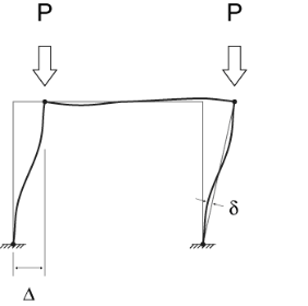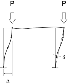
The P-Little Delta effect is essentially the destabilizing effect of individual member curvature on the axially loaded members. In practical applications, the effect of P-Little Delta will normally be significantly smaller than the P-Big Delta effect. The following figure demonstrates the displacements that cause the P-Delta and P-Little Delta effect in a typical moment frame.

The current implementation of P-Delta analysis does not directly account for the Little Delta effect. While this is true, the model can be easily adjusted to account for the effect as shown in the figure below.

Because RISA's P-Delta method is based entirely on nodal deflections, the introduction of nodes at the locations along the column where member displacement effects are at their maximum will adequately account for this effect.
There are a number of "benchmark" tests given in various publications to determine if a program is capable of properly considering this effect. Some of these benchmark problems (from the AISC Commentary) have been posted to our website with comparisons to theoretically correct solutions. These comparisons can be used as a basis for when the P-Little Delta effect is significant enough to consider in the analysis. They can also be used to determine how many intermediate nodes are required to adequately account for the effect at a given load level.
Note
The AISC manual specifically requires the consideration of the P-Little Delta effect. However, the Direct Analysis Method (AISC 360-16, Chapter C) inherently acknowledges that P-Little Delta may not be important by stating that it may be neglected when, “the axial loads in all members whose flexural stiffnesses are considered to contribute to the lateral stability of the structure” are less than 15% of the Elastic / Euler buckling load of the member.
This may seem like it would be a low axial force, but it can actually be a very large force greater than the total axial capacity of the column. Situations where this code provision may justify ignoring the P-Little Delta effect would include strong axis bending of a wide flange column with equal unbraced lengths in the strong and weak axes.
As of the 2014 edition, ACI 318 offers three options to account for slenderness and curvature in columns and walls (Section 6.2.6):
Both forms of second order analysis are more accurate than the moment magnification procedure, which is a hand calculation method intended to be used when computer analysis is not available. RISA does not have a true nonlinear solver though, so the program performs an Elastic Second Order Analysis using cracked section properties.
In order to meet the requirements of Section 6.7 (thereby meeting the requirements of Section 6.2.6) you must turn on P-Delta in the Load Combinations spreadsheet, and possibly add intermediate joints along the length of the columns. The Split Member tool can be used to add joints along the physical columns.
When ACI 318-08 and newer is used the slenderness effects are not neglected per the provisions of Section 10.10.1 (ACI 318-14 Section 6.2.5)
In order to meet the requirements of Section 6.7 (thereby meeting the requirements of Section 6.2.6) you must turn on P-Delta in the Load Combinations spreadsheet and include P-Delta for walls in the Model Settings. The effects of P-Little-Delta are accounted for in walls using the Non-Sway Moment Magnification Procedure of ACI 318-11 Section 10.10.6 or ACI 318-14 Section 6.6.4.5.